
1. Introduction to Electromagnetic Induction and AC Fundamentals
Hey junior! Let’s clear up a major funda. For ages, people thought electricity and magnetism were totally different, like pani puri and pizza. But in the early nineteenth century, legends like Oersted and Ampere showed they are actually cousins. Then came Michael Faraday and Joseph Henry, who proved that a varying magnetic field can "push" electrons to create a current. This magic is called Electromagnetic Induction (EMI).
NEET Checkpoint:
Which phenomenon involves generating current using varying magnetic fields?
(a) Electrostatic induction
(b) Magnetic flux
(c) Electromagnetic induction
(d) Electric polarization
✅ Answer: (c) Electromagnetic Induction — The sources define it as the generation of current by changing magnetic fields.
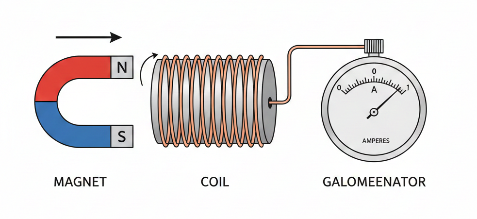
Think of it this way: relative motion is key. If you hold a magnet still near a coil, nothing happens. But move it fast, and boom—the galvanometer deflects! It’s like a rickshaw driver; they only earn when they are moving, not while waiting at the stand. This discovery led straight to the generators and transformers that power our lives today.
NEET Checkpoint:
Why do we use AC for our home mains instead of DC?
(a) AC is safer than DC
(b) AC voltage can be easily stepped up or down using transformers
(c) DC flows faster than AC
(d) AC produces more heat than DC
✅ Answer: (b) Efficiency and transformation — $AC$ can be easily and efficiently converted between voltages using transformers for long-distance transmission.
While $DC$ is a steady flow, the $AC$ voltage in our homes varies sinusoidally like a sine function. We prefer $AC$ because it can be "stepped up" to high voltages, making long-distance transmission much cheaper by reducing energy loss.
NEET Checkpoint:
What kind of function describes the time-variation of $AC$ voltage?
(a) Linear function
(b) Exponential function
(c) sine function
(d) Step function
✅ Answer: (c) Sine function — $AC$ voltage in mains supply varies like a sine function with time.
Figure below:
A clear diagram showing a bar magnet's North pole being pushed toward a conducting coil connected to a galvanometer, with an arrow indicating the motion and a needle deflection on the galvanometer.
Practice Questions:
- The experiments of Faraday and Henry (around 1830) led to the development of:
(a) DC Batteries
(b) Modern generators
(c) Static capacitors
(d) Resistors
✅ Answer: (b) — Their pioneering experiments led directly to the development of modern generators and transformers.
2. If a magnet is held stationary inside a closed coil, the induced current is:
(a) Maximum
(b) Minimum
(c) Zero
(d) Infinite
✅ Answer: (c) — The source states the galvanometer does not show any deflection when the magnet is held stationary.
Key Takeaway
EMI is the birth of current from changing magnetic fields. $AC$ voltage varies sinusoidally ($v = v_m \sin \omega t$) and is preferred for its easy transformation and economical transmission.
2. Magnetic Flux and Faraday's Law of Induction
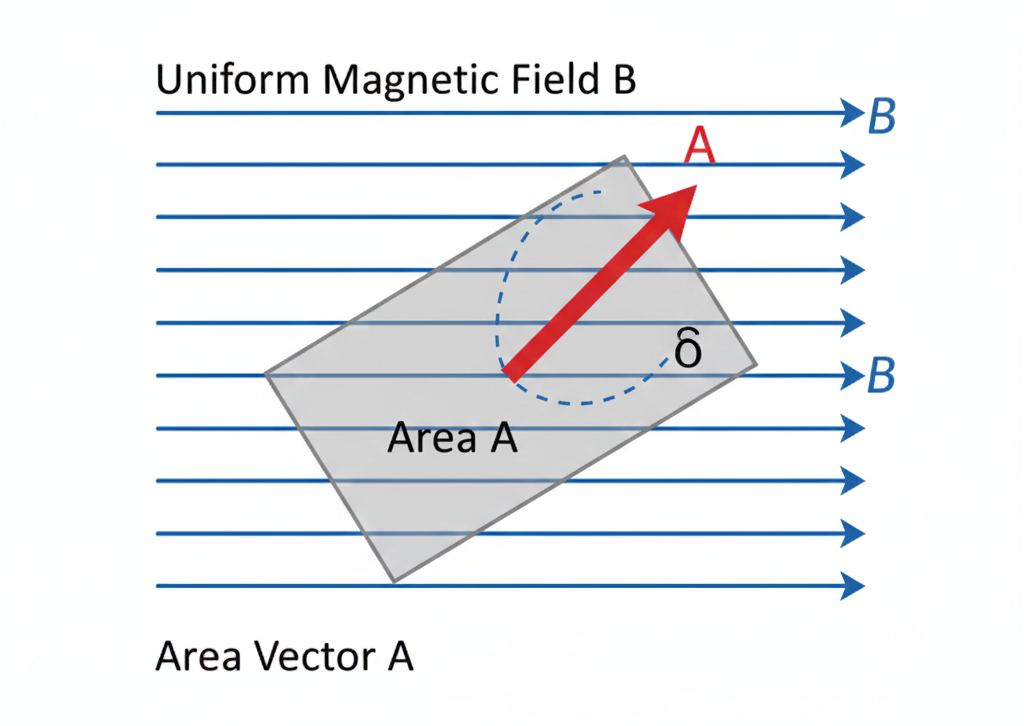
Now we’re getting into the real "magic" of physics. To understand how electricity is generated, we first need to clear up this Magnetic Flux ($\Phi_B$) funda. Think of flux as the total number of magnetic field lines "passing through" a specific area $A$.
Mathematically, for a uniform magnetic field $B$:
Here, $\theta$ is the angle between the magnetic field $\mathbf{B}$ and the area vector $\mathbf{A}$. If you tilt the area so it's parallel to the field ($\theta = 90^\circ$), the flux becomes zero!. The SI unit for this is the weber ($Wb$) or tesla metre squared ($T \cdot m^2$).
NEET Checkpoint:
Which of the following is the SI unit of magnetic flux?
(a) $T$
(b) $Wb$
(c) $H$
(d) $G$
✅ Answer: (b) $Wb$ — Also remembered as $T \cdot m^2$!.
Now, why does this matter? Because of Faraday’s Law! Faraday discovered that an electromotive force (EMF) is induced in a circuit whenever the magnetic flux through it changes with time. It’s like a "reaction" to the change. The magnitude of this induced EMF ($\epsilon$) is the rate of change of flux:
If you have a closely wound coil with $N$ turns, the total EMF is boosted:
Relatable Example: Imagine you're holding a mosquito bat. If you hold it flat against a swarm, you catch the most "mosquito flux". If you tilt it, fewer pass through. If you shake the bat back and forth rapidly, you're changing the flux—and in Faraday’s world, that movement is what generates the "spark" of EMF!
NEET Checkpoint:
A coil has $500$ turns and the flux changes by $0.2 Wb$ in $0.1 s$. What is the magnitude of induced EMF?
(a) 1000 V
(b) 100 V
(c) 500 V
(d) 2000 V
✅ Answer: (a) $1000 V$ — Using $|\epsilon| = N \frac{\Delta\Phi}{\Delta t} = 500 \times \frac{0.2}{0.1} = 1000 V$..
NEET Checkpoint:
Does a steady, unchanging magnetic flux induce an EMF?
(a) Yes, always
(b) Yes, only in superconductors
(c) No, only a changing magnetic flux induces EMF
(d) Yes, if the magnetic field is strong
✅ Answer: (c) No — Faraday’s law requires a change in flux over time ($d\Phi/dt$)..
Figure below:
A clear diagram showing a rectangular area A in a uniform magnetic field B, with an arrow indicating the area vector at an angle theta to the field lines.
Practice Question:
A loop of area $0.1 m^2$ is perpendicular to a $0.5 T$ field. If it is flipped to be parallel to the field in $0.5 s$, what is the average induced EMF?
(a) $0.1 V$
(b) $0.5 V$
(c) $1.0 V$
(d) $0.05 V$
✅ Answer: (a) $0.1 V$ — Initial flux $\Phi_i = 0.5 \times 0.1 = 0.05 Wb$. Final flux $\Phi_f = 0$. $\epsilon = \Delta\Phi/\Delta t = 0.05/0.5 = 0.1 V$..
Key Takeaway
Formula Summary
- Magnetic Flux: $\Phi_B = BA \cos \theta$
- Faraday’s Law (1 turn): $\epsilon = -\frac{d\Phi_B}{dt}$
- For $N$ turns: $\epsilon = -N \frac{d\Phi_B}{dt}$
- Units: $1 Wb = 1 T \cdot m^2$
3. Direction of Induced Current: Lenz's Law and Induced Currents
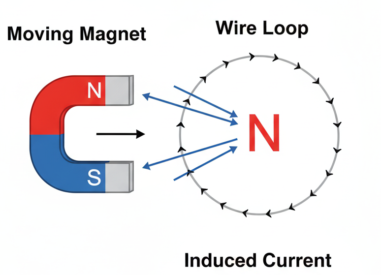
Hello, future doctors! Ready to master the most "rebellious" rule in physics? Lenz's law is basically the universe’s way of saying "No" to change. It provides the polarity of induced EMF, stating that it tends to produce a current that opposes the change in magnetic flux that produced it.
Think of it like a stubborn younger sibling or a "nosy neighbor" who always does the opposite of what you want. If you try to push the North-pole of a magnet into a coil, the coil immediately generates a current to create its own North-pole, trying to repel you. It’s like a fielder in a IPL match diving to stop a ball—the induced effect is always fighting the cause.
NEET Checkpoint:
If a North pole is moved away from a coil, what is the induced polarity of the coil's face?
(a) North
(b) South
(c) Neutral
(d) Alternates between North and South
✅ Answer: (b) South pole — It must oppose the "moving away" by trying to attract the magnet back.
Mathematically, this "opposition" is represented by that famous negative sign in Faraday’s law:
This isn't just about being difficult; it's fundamentally consistent with the Law of Conservation of Energy. If the induced current helped the change, the magnet would accelerate forever without any energy input—creating a perpetual motion machine! Instead, the mechanical work you spend pushing the magnet against this repulsive force is dissipated as Joule heating due to the induced current.
NEET Checkpoint:
The negative sign in $\epsilon = - \frac{d \Phi_{B}}{dt}$ is a manifestation of which law?
(a) Faraday’s law
(b) Ampere’s circuital law
(c) Lenz’s law
(d) Gauss’s law
✅ Answer:(c) Lenz’s Law — It indicates the direction of induced EMF opposes the flux change.
Figure below:
A clear diagram showing a bar magnet with its North pole moving toward a conducting loop, with arrows indicating the counter-clockwise induced current and the resulting repulsive North pole of the loop.
NEET Checkpoint:
What happens to the energy spent moving a magnet against the magnetic force of an induced current?
(a) It is destroyed
(b) It is stored permanently in the magnet
(c) It is converted into electrical energy and then into heat
(d) It has no effect
✅ Answer: (c) It is dissipated as Joule heat — Work done is converted into electrical energy and then heat.
Practice Question:
A metal ring is held horizontally and a bar magnet is dropped through it. The acceleration of the magnet will be:
(a) Equal to $g$
(b) More than $g$
(c) Less than $g$
(d) Zero
✅ Answer: (c) Less than $g$ — Because the induced current will create a force to oppose the magnet's falling motion (the change in flux).
Discrepancy Note: Source Not Found for "Eddy currents" in the provided Chapter 06 excerpts, though the term appears in the Unit 14 syllabus.
Key Takeaway
| Concept | Detail |
|---|---|
| Lenz's Law | Induced current opposes the change in flux. |
| Energy | Consistent with Conservation of Energy; work turns into Joule heat. |
| Math | Represented by the negative sign in $\epsilon = - \frac{d \Phi_{B}}{dt}$. |
4. Motional Electromotive Force (EMF)
Hey there, future doctors! Ready to get moving? Literally! In Motional EMF, we don't wait for the magnetic field to change—we take charge and move the conductor ourselves through a uniform, constant magnetic field.
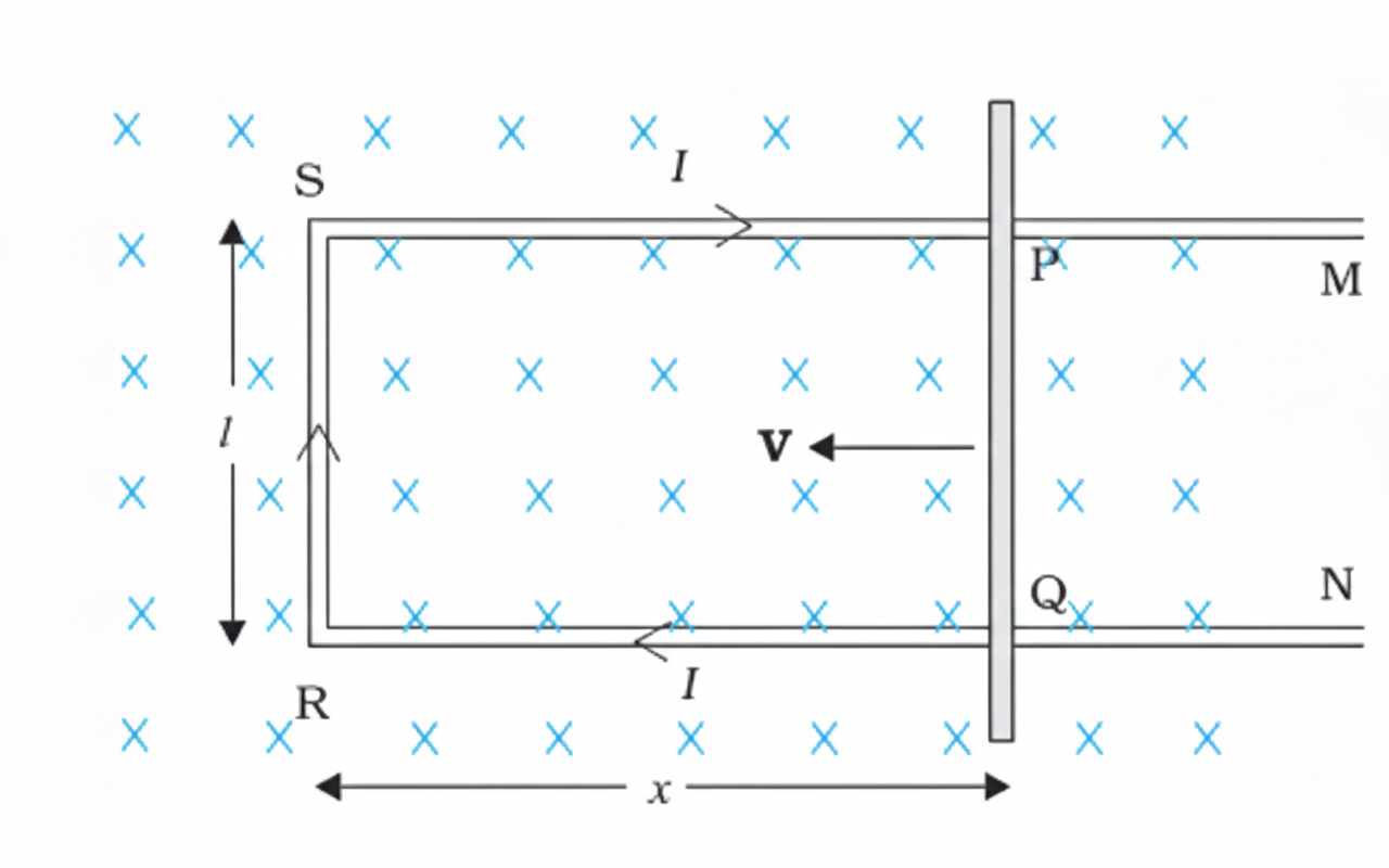
Imagine a straight conductor rod PQ of length l sliding on a U-shaped track with a constant velocity v. It’s placed in a uniform magnetic field $B$ that is perpendicular to the setup. As the rod moves, the area of the loop changes, which means the magnetic flux $\Phi_{B}$ enclosed by the circuit changes. According to our friend Faraday, this change induces an EMF. Here is the classic formula:
NEET Checkpoint:
A $2 m$ rod moves at $5 m/s$ perpendicular to a $0.5 T$ field. What is the induced EMF?
(a) $2 V$
(b) $5 V$
(c) $10 V$
(d) $0.5 V$
✅ Answer: (b) 5V — Just apply the simple funda: ϵ=Blv=0.5×2×5=5V
Relatable Example: Think of a rickshaw handle moving rapidly through the Earth's magnetic field while turning a corner in Delhi traffic. Since the handle is a conductor moving in a field, a tiny (and I mean tiny) EMF is induced across it! Don't worry, it won't give the driver a shock, but the physics is absolutely solid.
NEET Checkpoint:
Motional EMF can be explained using which force acting on free charges?
(a) Gravitational
(b) Lorentz
(c) Centripetal
(d) Frictional
✅ Answer: (b) Lorentz — Free charges $q$ moving with velocity $v$ in field $B$ experience a force $F = qvB$ .
You can also explain this using the Lorentz force. When the rod moves, the free charges inside move too. They feel a force $qvB$ pushing them toward one end. This work done per unit charge is exactly the EMF we calculated earlier!
But what if the conductor is stationary and the magnetic field is the one changing? Then, the force on the static charges must come from an induced electric field $E$. This shows how beautifully electricity and magnetism are linked.
NEET Checkpoint:
If a rod is stationary in a time-varying magnetic field, the induced EMF arises from:
(a) Lorentz force
(b) Induced electric field
(c) Static gravity
(d) Resistance
✅ Answer: (b) Induced electric field — Since velocity $v = 0$, the $qv \times B$ term vanishes, leaving only the electric field to act on charges.
Figure below:
A clear diagram showing a rectangular conductor PQRS where a movable arm PQ of length l moves with velocity v to the left, decreasing the area of the loop in a uniform magnetic field represented by crosses (into the page), with labels for l, x, and v.
Practice Question:
A metallic rod of length $L$ is rotated with angular frequency $\omega$ in a uniform magnetic field $B$ (normal to the plane). The EMF induced between the centre and the end is?
(a) $BLv$
(b) $\frac{1}{2}B\omega L^{2}$
(c) $B\omega L$
(d) Zero
✅ Answer: (b) — This is the standard result for a rotating conductor where we integrate the motional EMF $Bv dr$ along the length.
Key Takeaway
Motional EMF is induced by moving a conductor in a magnetic field.
The Big Formula:
$$\epsilon = Blv$$
It can be derived via Flux Change or the Lorentz Force ($F = qvB$). For stationary conductors, a changing magnetic field creates an induced electric field to move the charges.
5. The AC Generator (Dynamo)
Hey future doc! Let’s clear up the funda of the AC Generator, a "highly evolved machine" that powers everything from your phone charger to the hospital equipment you'll one day use. This device converts mechanical energy into electrical energy using the magic of electromagnetic induction.
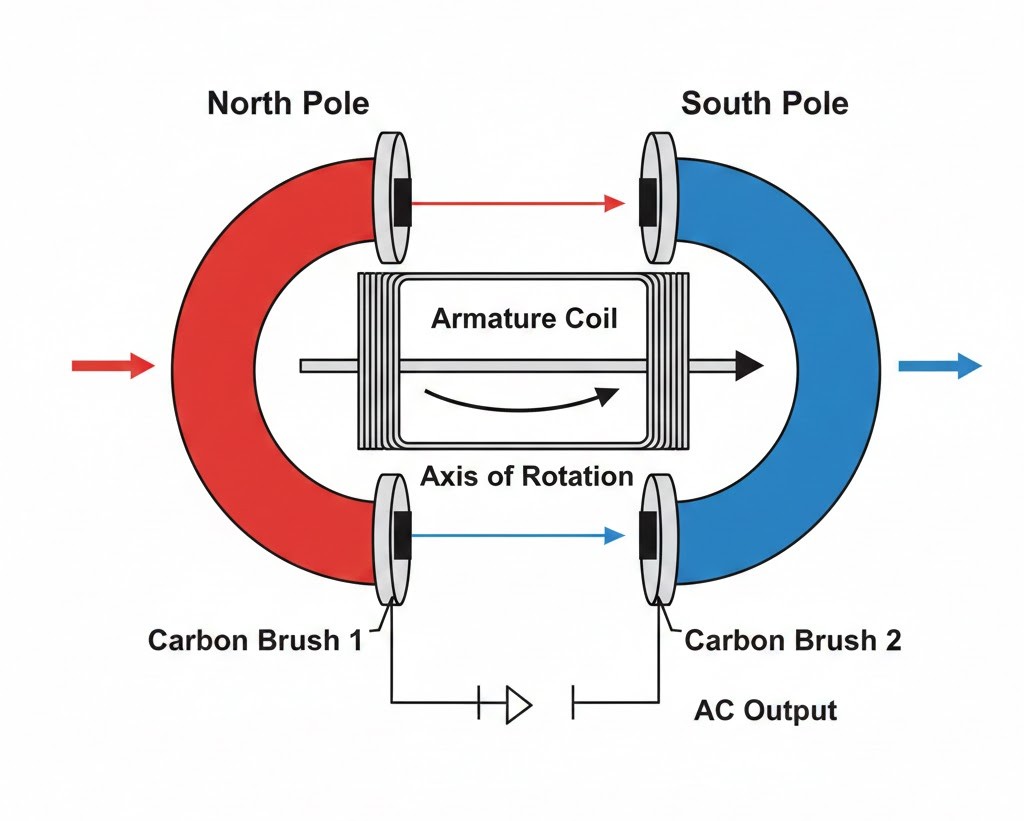
The setup is simple: a coil (called an armature) is mechanically rotated in a uniform magnetic field $B$. Imagine a local pani puri wallah spinning a small dynamo on his bicycle to light up his stall—that’s mechanical work turning into glowy goodness! As the coil rotates with a constant angular speed $\omega$, the magnetic flux through it keeps changing because the angle $\theta = \omega t$ between the area vector $A$ and magnetic field $B$ is shifting.
NEET Checkpoint:
At what angle $\theta$ is the induced EMF in an AC generator maximum?
(a) $0^\circ$
(b) $90^\circ$
(c) $180^\circ$
(d) $45^\circ$
✅ Answer: (b) $90^\circ$ — At $\theta = 90^\circ$, the rate of change of flux is greatest, giving us peak EMF.
The flux at any time $t$ is given by:
From Faraday’s law, the instantaneous induced EMF for a coil with $N$ turns is:
The maximum or peak value of this EMF is $\epsilon_0 = NBA\omega$. In India, our commercial generators hum at a frequency of $50~Hz$. Don't stress, yaar—just remember $NBA\omega$ is the "MVP" (Maximum Voltage Peak) here!
NEET Checkpoint:
What is the standard frequency of AC supply in India?
(a) $50~Hz$
(b) $25~Hz$
(c) $60~Hz$
(d) $100~Hz$
✅ Answer: (a) $50~Hz$ — In some countries like the USA, it's $60~Hz$, but we stick to 50.
NEET Checkpoint:
Which components connect the rotating armature to the external circuit?
(a) Field magnets
(b) Slip rings
(c) Armature core
(d) Brushes
✅ Answer: (d) Brushes — They ensure the current flows out even while the coil is spinning like a crazy cricket ball.
Figure below:
A clear diagram of an AC generator showing a rectangular armature coil between two magnetic poles, connected to slip rings and carbon brushes, with the axis of rotation marked.
Practice Question:
If an AC generator coil of 100 turns and area $0.1~m^2$ rotates at $0.5~rev/s$ in a $0.01~T$ field, what is the peak voltage $\epsilon_0$?
(a) $0.314~V$
(b) $3.14~V$
(c) $31.4~V$
(d) $0.0314~V$
✅ Answer: (a) $0.314~V$ — Use $\epsilon_0 = NBA(2\pi\nu)$. So, $100 \times 0.01 \times 0.1 \times 2 \times 3.14 \times 0.5 = 0.314~V$.
Key Takeaway
Formula Summary
- Magnetic Flux: $\phi_B = BA \cos \omega t$
- Instantaneous EMF: $\epsilon = \epsilon_0 \sin \omega t$
- Peak EMF: $\epsilon_0 = NBA\omega$
- Angular frequency: $\omega = 2\pi\nu$
6. Inductance: The Coil’s "Inertia" Funda
Hey there, future doctor! Ever wonder why current doesn't just jump to its maximum value the moment you flip a switch? It’s all thanks to a cool property called Inductance. Think of it as the "electrical inertia" of a circuit—it loves to oppose change.
In any coil, the total magnetic flux linked with the $N$ turns (called flux linkage) is directly proportional to the current $I$. We write this relationship as:
Here, $L$ is the inductance. Notice this: $L$ is a scalar quantity. It’s not picky about direction; it only cares about the "bulk" of the magnetic field linkage.
NEET Checkpoint:
Does inductance change if you increase the current flowing through the coil?
(a) Yes, inductance increases linearly with current
(b) Yes, inductance decreases with current
(c) No, inductance remains constant
(d) Inductance becomes zero at high current
✅ Answer: (c) No! — Inductance $L$ is a constant that depends only on the geometry of the coil and the material of the core.
Think of it like a heavy auto-rickshaw. It takes a lot of "oomph" to get it moving, and once it's rolling, it doesn't want to stop. That’s exactly how an inductor treats current!
The SI unit of inductance is the henry, denoted by $H$, named after the scientist Joseph Henry. If you're looking at dimensions for your notes, it's $[ML^{2}T^{-2}A^{-2}]$.
NEET Checkpoint:
What is the SI unit of inductance?
(a) Ohm (Ω)
(b) Tesla (T)
(c) Henry (H)
(d) Farad (F)
✅ Answer: Henry ($H$) — Named in honour of Joseph Henry who discovered induction in the USA.
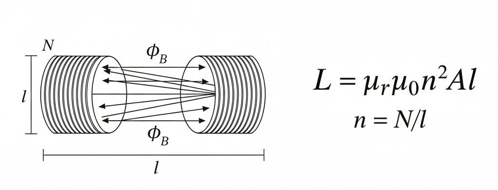
Figure below:
A clear diagram showing a long solenoid with $N$ turns, an area $A$, and length $l$, with magnetic field lines $\Phi_{B}$ passing through it, labelled with the formula $L = \mu_{r}\mu_{0}n^{2}Al$.
NEET Checkpoint:
If you put a soft iron core inside a solenoid, what happens to its inductance?
(a) It decreases
(b) It remains unchanged
(c) It increases
(d) It becomes zero
✅ Answer: It increases — Inductance depends on the intrinsic material properties (relative permeability $\mu_{r}$) of the core.
Practice Question:
The dimensions of inductance are:
(a) $[ML^{2}T^{-2}A^{-1}]$
(b) $[ML^{2}T^{-2}A^{-2}]$
(c) $[ML^{2}T^{-3}A^{-1}]$
(d) $[MLT^{-2}A^{-2}]$
✅ Answer: (b) — It is derived from the dimensions of flux divided by the dimensions of current.
Key Takeaway
- Flux Linkage Formula: $N\Phi_{B} = LI$
- Nature: Scalar quantity
- SI Unit: $H$ (henry)
- Dimensions: $[ML^{2}T^{-2}A^{-2}]$
- Depends on: Geometry and core material only.
7. Mutual Inductance ($M$)
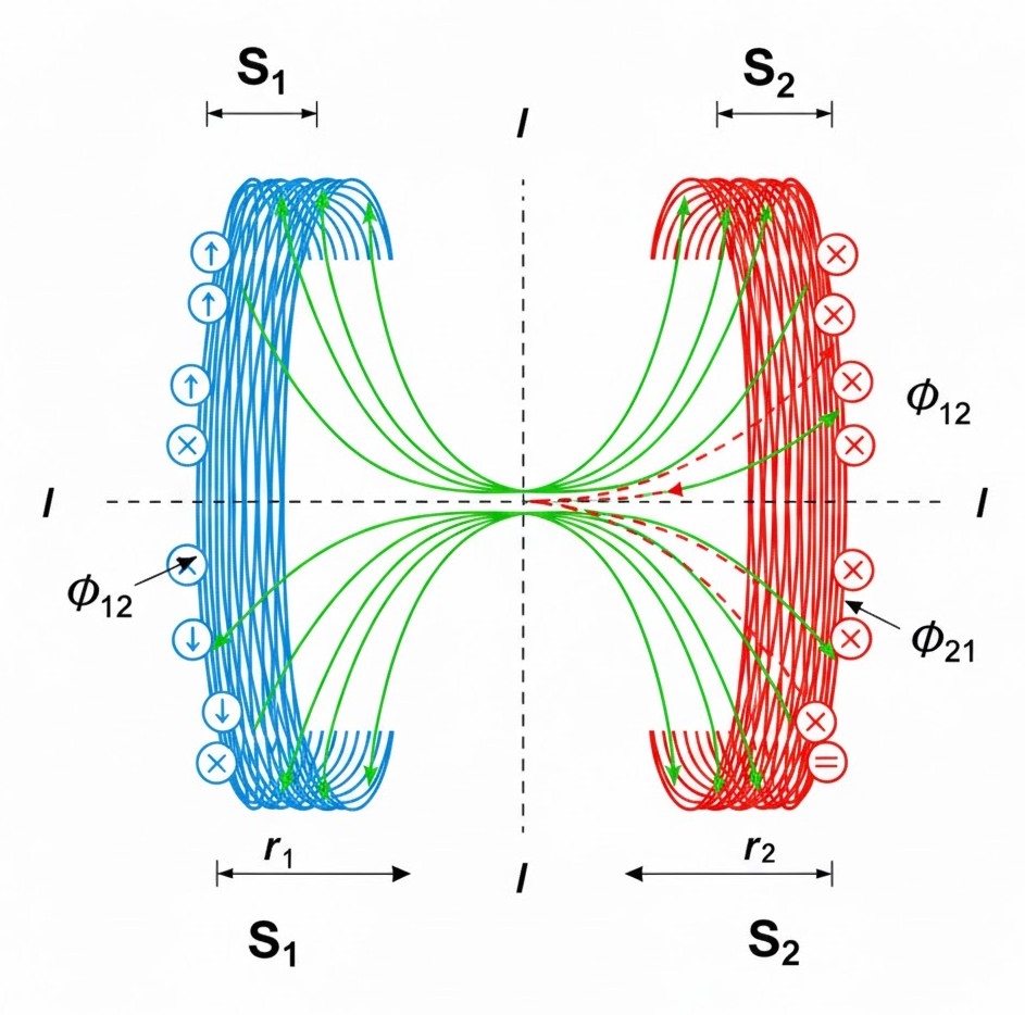
Arre junior, welcome to the "social" side of physics! While self-induction is all about a coil being stubborn with its own current, Mutual Induction is about the relationship between two neighbouring coils. When the current ($I_2$) in one coil changes, it changes the magnetic flux linked with a nearby coil, inducing an EMF ($\epsilon_1$) in it. It's basically like one student tapping their foot in a quiet exam hall and making everyone else nervous!
Here’s the main funda: the flux linkage in coil 1 is directly proportional to the current in coil 2, written as $N_1\Phi_1 = M_{12}I_2$. The constant $M$ is the Mutual Inductance. The induced EMF in the first coil is then:
NEET Checkpoint:
What is the SI unit of Mutual Inductance?
(a) Tesla
(b) Weber
(c) Henry
(d) Faraday
✅ Answer: (c) Henry — Arre, remember it’s the same as self-inductance! Both $L$ and $M$ share the unit $H$.
Relatable Indian Example: Imagine you and your friend are in a crowded Mumbai local train. If your friend starts swinging their heavy bag (changing current), you’ll definitely feel the "push" (induced EMF) even if you are standing still. The closer you stand (separation) and how your bags are angled (orientation), the more you feel it!
NEET Checkpoint:
If the mutual inductance of coil 1 with respect to coil 2 is $M_{12}$, and the reverse is $M_{21}$, what is the relation?
(a) $M_{12} > M_{21}$
(b) $M_{12} < M_{21}$
(c) $M_{12} = -M_{21}$
(d) $M_{12} = M_{21}$
✅ Answer: (d) $M_{12} = M_{21} = M$. This is called reciprocity, and it’s a total life-saver in tough calculations!.
The value of $M$ depends on the geometry (like radius and number of turns), the separation between coils, and their relative orientation. If you stuff an iron rod (high $\mu_r$) inside, $M$ shoots up.
Figure below:
A clear diagram showing two long co-axial solenoids, with an inner solenoid S1 of radius r1 and an outer solenoid S2 of radius r2, both of length l, illustrating mutual flux linkage.
NEET Checkpoint:
Does mutual inductance depend on the current flowing through the coils?
(a) Yes, it increases with current
(b) Yes, it decreases with current
(c) No, it is independent of current
(d) It depends only at high current
✅ Answer: No! Just like capacitance, $M$ only depends on geometry and material properties, not the current itself.
Practice Questions:
1. A pair of coils has a mutual inductance of $1.5\ H$. If the current in one coil changes from $0$ to $20\ A$ in $0.5\ s$, what is the change of flux linkage in the other?
(a) $30\ Wb$
(b) $40\ Wb$
(c) $10\ Wb$
(d) $1.5\ Wb$
✅ Answer: (a) $30\ Wb$. Use $N\Phi = MI = 1.5 \times 20 = 30\ Wb$. Easy-peasy!
2. Mutual inductance between two coils can be increased by:
(a) Decreasing the number of turns
(b) Increasing their separation
(c) Inserting a soft iron core
(d) Rotating them by $90^{\circ}$
✅ Answer: (c). Soft iron has high permeability ($\mu_r$), which boosts the magnetic coupling!.
Key Takeaway
Formula Summary
- Flux Linkage: $N_1\Phi_1 = M I_2$
- Induced EMF: $\epsilon_1 = -M \frac{dI_2}{dt}$
- Reciprocity: $M_{12} = M_{21} = M$
- Unit: $H$ (henry); Dimensions: $[ML^2T^{-2}A^{-2}]$
8. Self-Inductance ($L$)
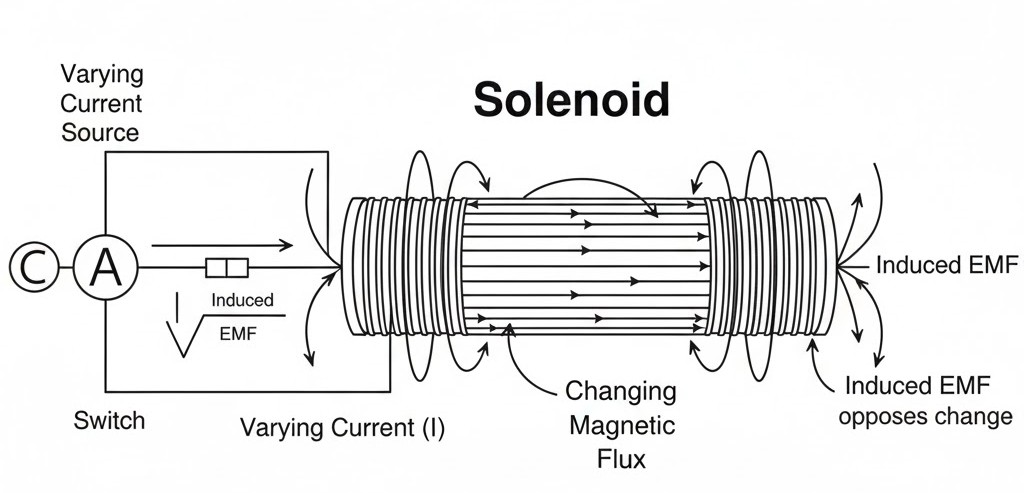
Listen up, juniors! We’ve seen coils influencing their neighbours, but now let’s talk about "self-love"—Self-Inductance ($L$). This phenomenon occurs when a single isolated coil induces an emf in itself because the current flowing through it changes. Think of it as the coil being stubborn; it hates any change in the current $I$ and fights back.
The total flux linkage $N\Phi_{B}$ is directly proportional to the current $I$, giving us our first big funda:
where $L$ is the self-inductance (or coefficient of self-induction) measured in henry ($H$).
NEET Checkpoint:
What is the SI unit of self-inductance?
(a) Weber
(b) Tesla
(c) Henry
(d) Ohm
✅ Answer: (c) Henry — Named after Joseph Henry, the guy who discovered this independently of Faraday!
When current varies, it induces a back EMF $\epsilon$ that opposes the change. Mathematically, it's:
This is why $L$ is called the electromagnetic analogue of mass in mechanics. Just like a heavy Mumbai local train is hard to start and hard to stop because of inertia, $L$ represents electrical inertia against the growth or decay of current.
NEET Checkpoint:
Self-inductance is the electromagnetic analogue of which mechanical quantity?
(a) Velocity
(b) Mass
(c) Force
(d) Acceleration
✅ Answer: (b) Mass — It provides the "stubbornness" or inertia against changing the state of current.
To establish a current $I$, work must be done against this back EMF, and this work is stored as magnetic potential energy. The energy stored is:
This looks exactly like the kinetic energy formula ($\frac{1}{2}mv^{2}$), doesn't it?
For a long solenoid with $n$ turns per unit length, area $A$, and length $l$, the formula is:
If you stuff it with a material of relative permeability $\mu_{r}$, it becomes:
Relatable Example:
Imagine you're trying to push a heavy stationary rickshaw. It resists your initial push (growth of current), but once it’s rolling, it resists stopping (decay of current). That "resistance to change" is exactly what $L$ does in a circuit!
NEET Checkpoint:
If you insert a soft iron rod ($\mu_{r} > 1$) into a solenoid, its self-inductance will:
(a) Decrease
(b) Stay same
(c) Increase
(d) Become zero
✅ Answer: (c) Increase — Look at the formula, $L$ is directly proportional to permeability.
Figure below:
A clear diagram of a long solenoid showing magnetic field lines inside and the connection to a varying current source to illustrate self-induction.
Practice Questions:
1. A circuit's current falls from $5.0\text{ A}$ to $0.0\text{ A}$ in $0.1\text{ s}$. If an average emf of $200\text{ V}$ is induced, what is the estimated self-inductance?
(a) $2\text{ H}$
(b) $4\text{ H}$
(c) $0.4\text{ H}$
(d) $40\text{ H}$
✅ Answer: (b) $4\text{ H}$ — Using $|\epsilon| = L\frac{\Delta I}{\Delta t}$, $200 = L \times (5/0.1)$, so $L = 200/50 = 4\text{ H}$.
2. The magnetic energy stored in an inductor is proportional to:
(a) $I$
(b) $I^{2}$
(c) $1/I$
(d) $\sqrt{I}$
✅ Answer: (b) $I^{2}$ — Energy $W = \frac{1}{2}LI^{2}$.
Key Takeaway
Formula Summary
- Flux Linkage: $N\Phi_{B} = LI$
- Induced Back EMF: $\epsilon = -L\frac{dI}{dt}$
- Stored Energy: $W = \frac{1}{2}LI^{2}$
- Solenoid Inductance: $L = \mu_{r}\mu_{0}n^{2}Al$
9. Characteristics of AC and RMS Values
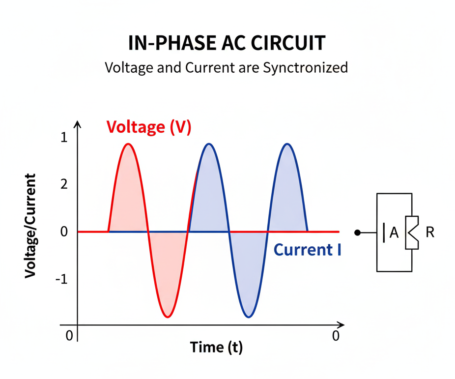
Arre, listen up, junior! AC isn't like your boring old DC cell; it’s sinusoidally varying, meaning it follows the rhythm of a sine function!. When you apply an AC voltage $v = v_{m} \sin \omega t$ to a resistor $R$, the resulting current $i$ is $i = i_{m} \sin \omega t$, where the peak current is $i_{m} = v_{m}/R$. Here’s the main funda: in a purely resistive circuit, voltage and current are best friends—they are perfectly in phase. This means they hit their peaks and zeros at the exact same time, as you can see in the graphs!.
NEET Checkpoint:
What is the phase difference between $v$ and $i$ in a pure resistor?
(a) $0^{\circ}$
(b) $30^{\circ}$
(c) $45^{\circ}$
(d) $90^{\circ}$
✅ Answer: (a) $0^{\circ}$ — They are in phase, like two dancers perfectly in sync!.
Now, why do we talk about RMS? Because if you average the current over a full cycle, you get a big fat zero!. But does that mean your toaster won't heat up? No way, yaar! Joule heating depends on $i^{2}R$, and since $i^{2}$ is always positive, energy is definitely dissipated. The RMS Current ($I$) is defined as $I = i_{m}/\sqrt{2} \approx 0.707 i_{m}$. Physically, the RMS current is the equivalent DC current that produces the same average power loss due to Joule heating, expressed as $P = I^{2}R$. Similarly, the RMS Voltage ($V$) is $V = v_{m}/\sqrt{2}$.
Think of it like your home's $220 V$ supply; that’s the "effective" RMS value, but the actual peak voltage $v_{m}$ is a shocking $311 V$!. It’s like a spicy pani puri—the "average" heat might be okay, but that "peak" spice will definitely make you jump!
NEET Checkpoint:
What is the average current of AC over a full cycle?
(a) Maximum current
(b) RMS current
(c) Zero
(d) Half of maximum current
✅ Answer: (c) Zero — The positive and negative halves cancel out perfectly!.
NEET Checkpoint:
If the peak voltage is $100 V$, what is the RMS voltage?
(a) $70.7 V$
(b) $100 V$
(c) $50 V$
(d) $141.4 V$
✅ Answer: (a) $70.7 V$ — Just multiply the peak by $0.707$ or divide by $\sqrt{2}$.
Figure below:
A clear diagram showing two overlapping sine waves on a graph of voltage/current vs. time. Both waves should reach their maximum, minimum, and zero points at the same instances to illustrate that they are in phase in a resistive circuit.
Practice Questions:
- A light bulb is rated $100 W$ for a $220 V$ AC supply. The resistance $R$ is:
(a) $2.2 \Omega$
(b) $484 \Omega$
(c) $100 \Omega$
(d) $311 \Omega$
✅ Answer: (b) $484 \Omega$ — Use $R = V^{2}/P = (220)^{2}/100 = 484 \Omega$.
2. The RMS current is also known as:
(a) Peak current
(b) Instantaneous current
(c) Effective current
(d) Average current
✅ Answer: (c) Effective current — It tells us the DC equivalent for power.
Key Takeaway: AC & RMS Basics
- Voltage: $v = v_{m} \sin \omega t$
- Current: $i = i_{m} \sin \omega t$, where $i_{m} = v_{m}/R$
- Phase: $\phi = 0$ (In phase for resistors)
- RMS Values: $I = \frac{i_{m}}{\sqrt{2}}$ and $V = \frac{v_{m}}{\sqrt{2}}$
- Average Power: $P = I^{2}R$
10. Phasor Diagrams for AC Circuit Analysis
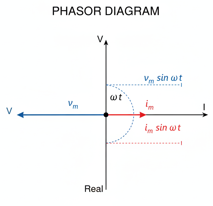
Arre junior, don't let those wiggly sine waves make you dizzy! To simplify AC, we use a super cool trick called phasors. Think of a phasor as a vector that loves to dance; it rotates about the origin with an angular speed of $\omega$. While it spins, its length stays constant, representing the amplitude or peak value (like $v_m$ or $i_m$) of our voltage or current.
Now, why do we care about a rotating arrow? Because its projection on the vertical axis gives us the instantaneous value at any moment $t$. It’s like watching the shadow of a giant wheel at a Mela (fair)—the height of the shadow tells you where the cabin is right now!
NEET Checkpoint:
What does the vertical component of a phasor represent?
(a) RMS value of the quantity
(b) Average value of the quantity
(c) Instantaneous value of the quantity
(d) Peak value of the quantity
✅ Answer: (c) The instantaneous value of the AC quantity (voltage or current).
In a purely resistive circuit, life is simple. The voltage and current phasors are like best friends—they are parallel, meaning they rotate together with a phase angle of zero. They reach their maximum and zero points at the exact same time.
NEET Checkpoint:
In a resistive AC circuit, the phase difference between voltage and current is?
(a) $90^\circ$
(b) $45^\circ$
(c) $180^\circ$
(d) Zero
✅ Answer: (d) Zero—they are perfectly "in phase".
NEET Checkpoint:
If the angular frequency of the AC source increases, what happens to the rotation speed of the phasor?
(a) Decreases
(b) Remains constant
(c) Becomes zero
(d) Increases
✅ Answer: (d) It increases, as the phasor rotates with angular speed $\omega$.
Relatable Example: Imagine you and your friend are pedalling a bicycle at a Pani Puri stall. If you both push the pedals down at the same time, you are "in phase" like a resistive circuit!
Figure below:
A clear phasor diagram showing a voltage phasor V and a current phasor I as arrows originating from the center, both pointing in the same direction at an angle $\omega t$ from the horizontal axis. Include dashed lines showing their projections $v_m \sin \omega t$ and $i_m \sin \omega t$ on the vertical axis.
Practice Questions:
- A phasor is a rotating vector used to represent:
(a) DC quantities
(b) Sinusoidally varying AC quantities
(c) Constant magnetic fields
(d) Average power
✅ Answer: (b) — Phasors are specifically designed to handle the harmonic time dependence of AC.
2. The magnitude of a phasor in an AC circuit represents:
(a) RMS value
(b) Average value
(c) Peak value
(d) Instantaneous value
✅ Answer: (c) — The length of the "arrow" is always the maximum possible value, $v_m$ or $i_m$.
Key Takeaway
Phasors are rotating vectors where:
- Length = Peak Value ($v_m$ or $i_m$)
- Vertical Projection = Instantaneous Value
- Rotation Speed = Angular Frequency ($\omega$)
- Resistive Circuit = Zero phase difference (parallel)
11. Inductive Reactance ($X_L$)
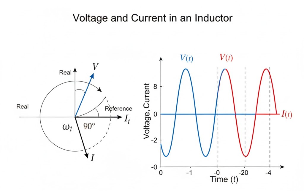
Hey there, future doctors! Let’s clear up this funda about how an inductor behaves when you throw some AC at it. In a purely inductive circuit, the inductor is like that one friend who is always late to the party; the current ($i$) lags the voltage ($v$) by a phase angle of $\pi/2$ or one-quarter of a cycle.
NEET Checkpoint:
In a pure inductor, if voltage is $v = v_m \sin \omega t$, what is the phase of the current?
(a) $\omega t $
(b) $\omega t + \pi/2$
(c) $\omega t - \pi/2$
(d) $\omega t - \pi$
✅ Answer: (c) $\omega t - \pi/2$ — Current lags behind, so we subtract the phase!
Think of Inductive Reactance ($X_L$) as the "AC version" of resistance. It’s the opposition an inductor offers to the flow of AC, and it’s defined as:
where $\omega$ is the angular frequency and $L$ is the self-inductance. Just like resistance, $X_L$ is measured in ohms ($\Omega$). The current amplitude is then given by $i_m = \frac{v_m}{X_L}$.
Notice this: $X_L$ is directly proportional to the frequency ($f$) of the AC. If you increase the frequency, the inductor gets even grumpier and blocks the current more! It’s like trying to navigate a rickshaw through a crowded Chandni Chowk bazaar; the faster you try to go, the more the crowd (reactance) pushes back.
NEET Checkpoint:
What happens to $X_L$ if the frequency of the AC source is doubled?
(a) Becomes half
(b) Remains unchanged
(c) Becomes four times
(d) Becomes double
✅ Answer: (d) It doubles — Since $X_L = 2\pi fL$, they are best friends (directly proportional)!
Now, here’s the best part: the average power supplied to a pure inductor over a complete cycle is zero. Because the current and voltage are out of phase, the inductor takes energy in one half-cycle and gives it all back in the next. It’s like a "wattless" transaction—all work and no pay!
Figure below:
A phasor diagram showing voltage phasor V at an angle ωt and current phasor I lagging behind it by 90 degrees, with a corresponding sine wave graph showing the voltage peak occurring before the current peak.
NEET Checkpoint:
What is the average power dissipated in a purely inductive circuit?
(a) Maximum
(b) Non-zero
(c) Depends on frequency
(d) Zero
✅ Answer: (d) Zero — No energy is lost as heat in a pure inductor; it's very efficient, yaar!
Practice Questions:
- A $25.0$ mH inductor is connected to a $220$ V, $50$ Hz source. The inductive reactance is approximately:
(a) $5.50$ $\Omega$
(b) $7.85$ $\Omega$
(c) $10.2$ $\Omega$
(d) $12.5$ $\Omega$
✅ Answer: (b) — Use $X_L = 2\pi fL$. So, $2 \times 3.14 \times 50 \times 25 \times 10^{-3} \approx 7.85$ $\Omega$.
2. The current in a purely inductive AC circuit:
(a) Leads voltage by $\pi/2$
(b) Is in phase with voltage
(c) Lags voltage by $\pi/2$
(d) Lags voltage by $\pi$
✅ Answer: (c) — Remember, the inductor "induces" a delay!
Key Takeaway
Formula Summary
- Inductive Reactance: $X_L = \omega L = 2\pi fL$
- Current Amplitude: $i_m = \frac{v_m}{X_L}$
- Phase Difference: Current lags voltage by $\pi/2$ ($90^\circ$)
- Average Power: $P_{avg} = 0$
12. Capacitive Reactance ($X_C$)
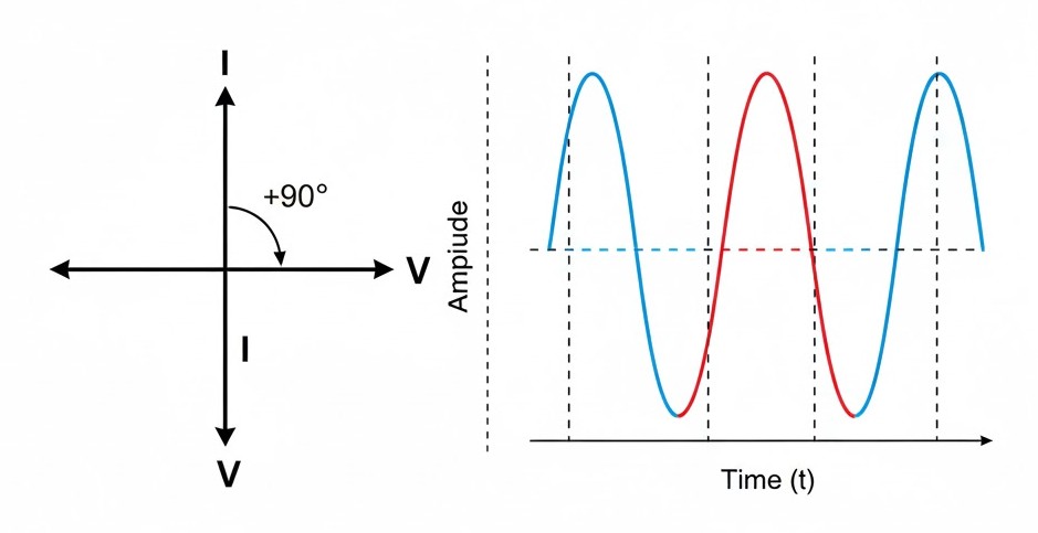
Ready to tackle the "attitude" of a capacitor? In a purely capacitive AC circuit, the current $i$ is basically that over-excited student who reaches the coaching centre before the gates even open. Specifically, the current leads the voltage $v$ by a phase angle of $\pi/2$ or $90^{\circ}$.
Think of it like a local bus during rush hour: the crowd (current) starts surging toward the door even before the bus (voltage) has actually stopped at the stand! Notice this: while the voltage is still trying to build up, the current has already hit its peak.
NEET Checkpoint:
In a purely capacitive circuit, what is the phase relationship between $i$ and $v$?
(a) $i$ lags $v$ by $\pi/2$
(b) $i$ and $v$ are in phase
(c) $i$ leads $v$ by $\pi/2$
(d) $v$ leads $i$ by $\pi$
✅ Answer: (c) $i$ leads $v$ by $\pi/2$ — Current is the "early bird" topper here!
The opposition a capacitor offers to the flow of AC is called Capacitive Reactance ($X_C$). Here's the trick: it's measured in ohms ($\Omega$), just like resistance, but its value depends on the frequency $\nu$ of the source.
The current amplitude is given by $i_m = \frac{v_m}{X_C}$. Since $X_C$ is inversely proportional to frequency and capacitance, doubling the frequency will actually cut the reactance in half.
NEET Checkpoint:
If you connect a capacitor to a DC source ($\nu = 0$), what is its reactance?
(a) Zero
(b) Finite
(c) Infinite
(d) Depends on capacitance
✅ Answer: (c) Infinite — Since $\nu = 0$, $X_C$ becomes $1/0$, which is infinite. This is why a capacitor blocks DC after getting fully charged!
Now, why does this matter? Even though the capacitor is constantly charging and discharging, it doesn't actually "eat" energy. The average power supplied over a complete cycle is zero. It’s like a friend who borrows 100 bucks and returns it by the end of the day—no profit, no loss!
NEET Checkpoint:
What is the average power dissipated in a pure capacitor?
(a) Maximum
(b) Non-zero constant
(c) Depends on frequency
(d) Zero
✅ Answer: (d) Zero — Because the phase difference is $90^{\circ}$, the power factor is zero, and no net energy is consumed.
Figure below:
A phasor diagram for a purely capacitive circuit showing a horizontal voltage phasor V and a vertical current phasor I pointing upwards (90 degrees ahead), with a side-by-side graph of their respective sine waves where the current wave starts at its peak when the voltage wave is at zero.
Practice Questions:
1. A $15.0~\mu F$ capacitor is connected to a $220~V, 50~Hz$ source. Calculate its capacitive reactance.
(a) $106~\Omega$
(b) $212~\Omega$
(c) $311~\Omega$
(d) $484~\Omega$
✅ Answer: (b) $212~\Omega$ — Use $X_C = 1 / (2\pi \nu C)$. Plug in $50~Hz$ and $15 \times 10^{-6}~F$ to get approximately $212~\Omega$.
2. If the frequency of the AC source is doubled, the rms current in a purely capacitive circuit will:
(a) Be halved
(b) Remain the same
(c) Double
(d) Quadruple
✅ Answer: (c) Double — Since $X_C \propto 1/\nu$, doubling frequency halves the reactance, which doubles the current $I = V/X_C$.
Key Takeaway
Formula Summary
- Capacitive Reactance: $X_C = \frac{1}{\omega C} = \frac{1}{2\pi \nu C}$
- Current Amplitude: $i_m = \frac{v_m}{X_C}$
- Phase Difference: $\phi = \pi/2$ ($i$ leads $v$)
- Average Power: $P_{avg} = 0$
13. Series LCR Circuit and Impedance ($Z$)
Hey champ! Ready to tackle the "Big Boss" of AC circuits? When a Resistor ($R$), an Inductor ($L$), and a Capacitor ($C$) all join a series party with an AC source, things get a bit spicy. To find the vibe of this circuit, we use Kirchhoff's loop rule, which gives us the instantaneous voltage relation:
Don't let the calculus scare you, yaar! We simplify this using Impedance ($Z$), which is the total effective "nakhra" (opposition) the circuit offers to the AC current.
NEET Checkpoint:
What is the SI unit of Impedance ($Z$)?
(a) Ohm (Ω)
(b) Henry (H)
(c) Farad (F)
(d) Siemens (S)
✅ Answer: Ohm ($\Omega$) — Just like resistance, it's all about opposing the flow!
We calculate this total opposition using this killer formula:
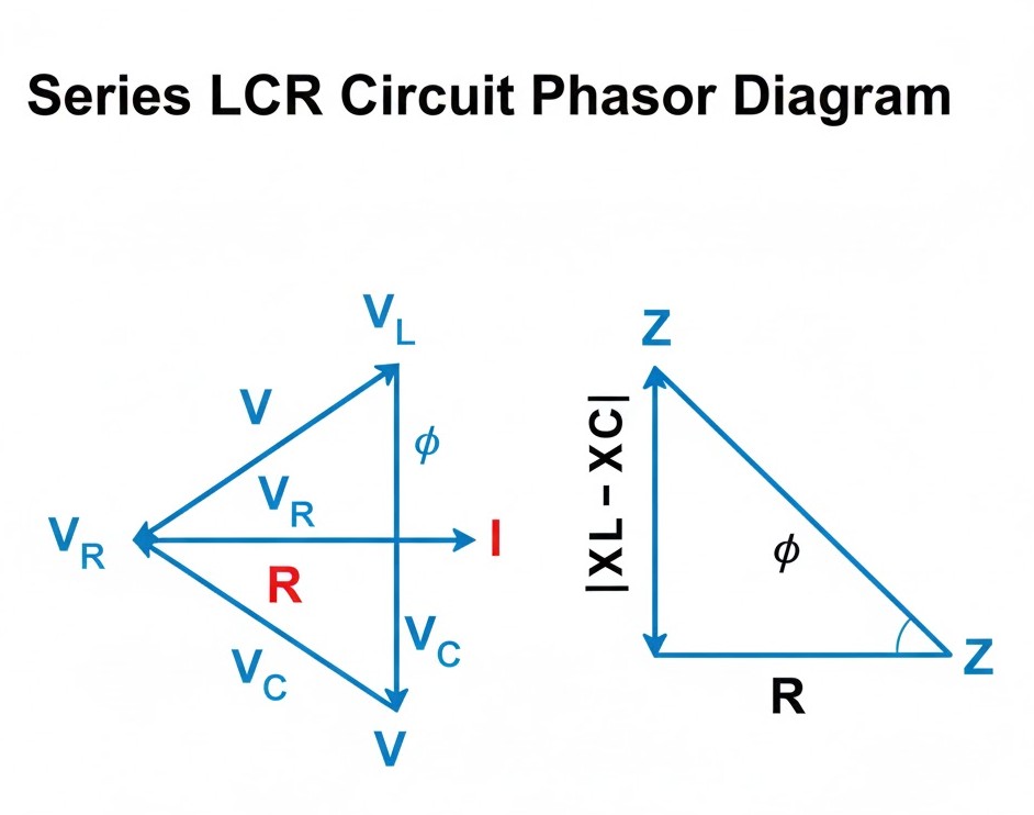
Here, the current amplitude is simply $i_m = \frac{v_m}{Z}$. But remember, in this trio, the current and voltage aren't always "in sync." The phase angle ($\phi$) tells us how much the current leads or lags behind the source voltage:
NEET Checkpoint:
If $X_C > X_L$, does the current lead or lag the voltage?
(a) Current lags voltage
(b) Current leads voltage
(c) Current and voltage are in phase
(d) Phase difference is 90^o
✅ Answer: (b) Leads — The circuit is predominantly capacitive, and like an over-excited student, the current rushes ahead!
Relatable Indian Example: Imagine three friends on a single scooter. The Resistor is the driver (steady), the Inductor is the sleepy guy at the back (lagging), and the Capacitor is the hyper kid in the middle (leading). Their combined "struggle" to move through traffic is the Impedance $Z$!
Figure below:
A clear phasor diagram for a series LCR circuit showing current I, voltage phasors V_R, V_L, V_C, and the resultant source voltage V forming an impedance triangle.
NEET Checkpoint:
At resonance, $X_L = X_C$. What happens to $Z$?
(a) $ Z=R $
(b) $Z = X_L$
(c) $Z = X_C$
(d) $Z = 0$
✅ Answer: $Z = R$ — The inductive and capacitive effects cancel out, leaving only the resistor to face the music!
Practice Question:
A series LCR circuit has $R = 3 \Omega$, $X_L = 8 \Omega$, and $X_C = 4 \Omega$. Calculate $Z$.
(a) $7 \Omega$
(b) $5 \Omega$
(c) $1 \Omega$
(d) $15 \Omega$
✅ Answer: (b) $5 \Omega$ — Use $Z = \sqrt{3^2 + (4-8)^2} = \sqrt{9 + 16} = 5 \Omega$. Simple math, big marks!
Key Takeaway
Formula Summary
- Impedance: $Z = \sqrt{R^2 + (X_C - X_L)^2}$
- Current Amplitude: $i_m = \frac{v_m}{Z}$
- Phase Angle: $\tan \phi = \frac{X_C - X_L}{R}$
14. Resonance in LCR Circuits
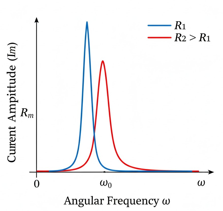
Listen up, junior, because this topic is a NEET favourite!. Resonance is like that perfect moment in a cricket match when the bat hits the ball exactly at the "sweet spot" for a massive six. In a series LCR circuit, resonance occurs when the voltages across the inductor and capacitor cancel each other out because they are out of phase. This happens when the inductive reactance $X_L$ and capacitive reactance $X_C$ are equal.
This magic happens at a specific resonant angular frequency ($\omega_0$):
At this frequency, the impedance $Z$ is at its absolute minimum value, $Z = R$. Because the impedance is so low, the current amplitude $i_m$ shoots up to its maximum value, $i_m = v_m/R$. Also, the phase angle $\phi$ becomes zero, meaning the current and voltage are perfectly in sync, just like a well-coordinated Bollywood dance routine. You’ll see this funda applied in everything from tuning your radio to those metal detectors at the airport that beep when you forget your coins.
NEET Checkpoint:
What is the value of the phase angle at resonance?
(a) $\phi = 0$
(b) $ϕ=30 ∘$
(c) $ϕ=60∘$
(d) $ϕ=90∘$
✅ Answer: $\phi = 0$ — The reactances cancel out, leaving the circuit purely resistive.
NEET Checkpoint:
Can resonance occur in a simple RC circuit?
(a) Yes, at low frequency
(b) Yes, at high frequency
(c) No, because there is no inductance
(d) Yes, at any frequency
✅ Answer: (c) No, resonance requires both $L$ and $C$ to be present to allow for voltage cancellation.
Figure below:
A line graph showing current amplitude $i_m$ on the vertical axis and angular frequency $\omega$ on the horizontal axis, displaying a sharp peak at the resonant frequency $\omega_0$ for two different resistance values.
NEET Checkpoint:
At resonance, the circuit's impedance is equal to?
A. R (Resistance)
B. $X_L$ (Inductive Reactance)
C. $X_C$ (Capacitive Reactance)
D. $X_L + X_C$
✅ Answer: The resistance $R$ — This is the minimum possible impedance for the circuit.
Practice Questions:
If the capacitance $C$ in a resonant LCR circuit is made four times, the new resonant frequency will be:
(a) Doubled
(b) Halved
(c) Four times
(d) Unchanged
✅ Answer: (b) Halved — Since $\omega_0 = 1/\sqrt{LC}$, increasing $C$ by 4 times results in $\sqrt{4}$ in the denominator, which is 2.
Key Takeaway
Formula Summary
- Condition: $X_L = X_C$.
- Resonant Frequency: $\omega_0 = \frac{1}{\sqrt{LC}}$.
- Impedance: $Z = R$ (Minimum).
- Max Current: $i_m = \frac{v_m}{R}$.
15. AC Power, Wattless Current, and Transformers
Hello, junior! Ready to master the "power" moves of physics? Let's clear up the funda of how AC circuits actually expend energy and how we shift voltages around like a pro.
In an AC circuit, the average power ($P$) supplied by the source isn't just $VI$. It depends on the phase angle $\phi$:
Here, $\cos \phi$ is the power factor, and it measures how close the circuit is to expending maximum power. Think of it as the "efficiency meter" of your circuit. In a purely resistive circuit, $\phi = 0$, so $\cos \phi = 1$, and you get maximum power dissipation.
NEET Checkpoint:
What is the power factor of a purely capacitive circuit?
(a) 0
(b) 1
(c) 0.5
(d) -1
✅ Answer: (a) 0 — In purely reactive circuits (only $L$ or $C$), $\phi = \pi/2$, so $\cos \phi = 0$, meaning no power is dissipated.
This leads to a cool concept: wattless current. In these zero-dissipation reactive circuits, current flows, but it doesn't "eat" any power. It’s like a cricketer taking a long run-up but not hitting the ball—lots of movement, zero runs!
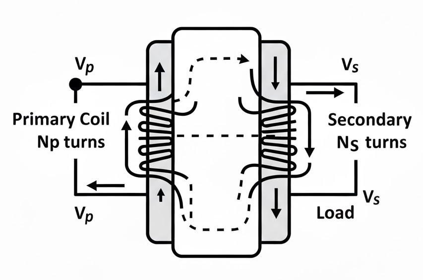
Now, let's talk about Transformers. These geniuses use mutual induction to change AC voltage from one value to another.
NEET Checkpoint:
Transformers can change DC voltage?
(a) True
(b) False
✅ Answer: False — They rely on alternating magnetic flux from AC to work.
For an ideal transformer (no energy leaks!), we use these ratios:
Notice the twist? Voltage follows the turns ratio, but current is the inverse.
NEET Checkpoint:
In a step-up transformer ($N_s > N_p$), what happens to the current?
(a) Increases
(b) Decreases
(c) Remains the same
(d) Becomes zero
✅ Answer: (b) It decreases — To keep power constant ($P = VI$), if voltage goes up, current must go down.
Indian Example: Imagine a Pani Puri stall. The big container of spiced water is your Primary. Every time the vendor dips a small cup (Secondary), he’s "transforming" a large volume into small, high-pressure servings for you!
figure below:
A clear diagram of a transformer showing a rectangular soft-iron core with a primary coil of $N_p$ turns on the left and a secondary coil of $N_s$ turns on the right, labeled with $V_p$ and $V_s$.
Practice Question:
An ideal transformer has 100 turns in the primary and 400 turns in the secondary. If the input voltage is $220 V$, the output voltage is:
(a) $55 V$
(b) $880 V$
(c) $220 V$
(d) $440 V$
✅ Answer: (b) $880 V$. Using $\frac{V_s}{V_p} = \frac{N_s}{N_p}$, we get $V_s = 220 \times (\frac{400}{100}) = 880 V$.
Key Takeaway
Formula Summary
- Average Power: $P = V I \cos \phi$
- Power Factor: $\cos \phi = \frac{R}{Z}$
- Transformer Ratio: $\frac{V_s}{V_p} = \frac{N_s}{N_p} = \frac{i_p}{i_s}$